Supply and extract
Show where air enters, how it reaches intended zones and where it leaves.
A basement has no natural breeze to rely on. Its air path is planned, powered and coordinated through a crowded ceiling where ducts, beams, lights and signs compete for room.
A conceptual guide to spatial relationships, not ventilation design advice or approval.
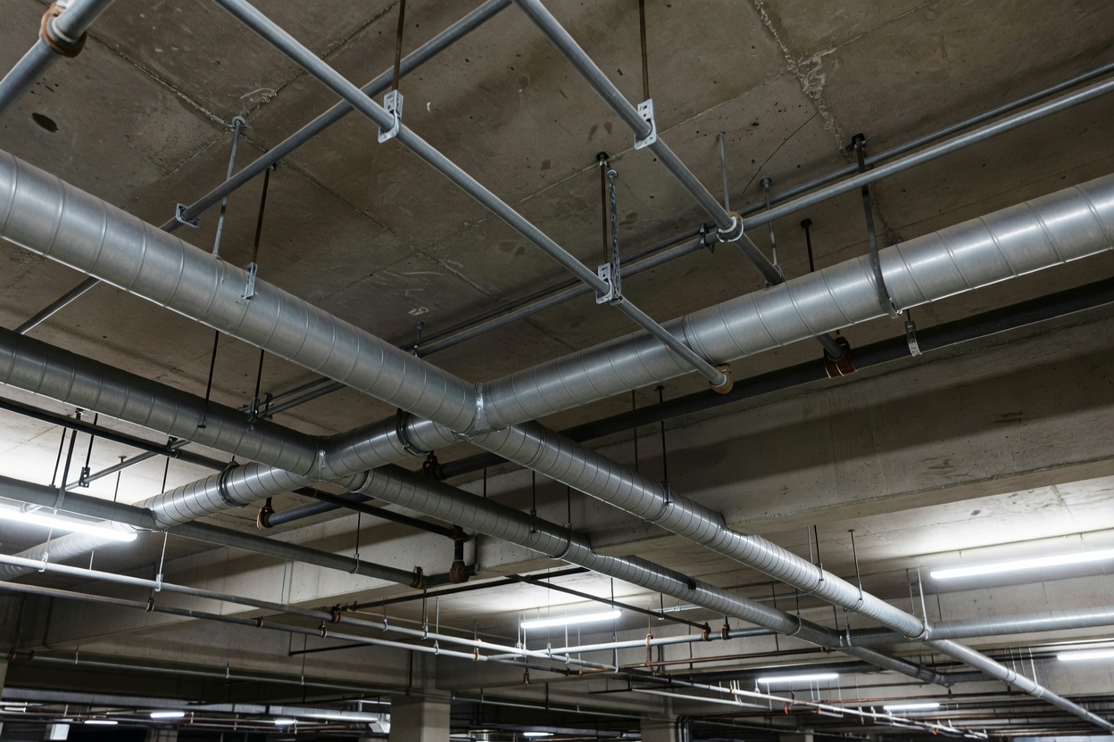
Ventilation is easier to understand when drawn as a continuous journey rather than as isolated fans or grilles. Air enters from an intake, travels through a distribution strategy, mixes with the occupied space, and leaves through exhaust points. The route also has to account for the building’s intended operation and emergency strategy. A basement may be divided into zones by walls, ramps, doors, beams and changes of level, so a supply point in one area does not automatically serve a distant corner.
At the earliest planning stage, the architectural question is where the major air routes can pass without compromising headroom or circulation. Ducts occupy valuable space above vehicles and below the structural slab. Large ducts may need to cross beams, wrap around a core or use a dedicated service zone. In some projects, distributed systems reduce dependence on extensive ductwork; in others, centralised routes are more appropriate. The choice depends on the scheme and requires a competent building-services designer.
Normal ventilation and smoke control are related but distinct design tasks. Everyday ventilation addresses operational air quality and the building’s use. Fire and smoke strategy addresses a different set of conditions, interfaces and operating assumptions. Designers must coordinate them with compartmentation, escape routes, fire-service access, controls and the project’s applicable fire safety requirements. A ceiling sketch that simply places an extract fan over every area does not demonstrate either a complete normal ventilation system or a compliant smoke-control approach.
In the United Kingdom, Approved Document B provides a regulatory reference for fire safety in buildings, and the relevant edition and project context matter. Building regulations, fire strategy, engineering standards and local authority requirements should be checked by the responsible professionals. Guidance from organisations including the Society of Fire Protection Engineers and Chartered Institution of Building Services Engineers can help frame specialist discussions, but a webpage cannot replace a design calculation or formal review.
Architectural sections reveal the real contest for depth. A car needs a safe and comfortable clear envelope; structure needs depth to span; ducts need space to move air; lights and signs need locations that remain visible. A false ceiling can conceal services, but it also lowers the perceived height and may hide useful orientation cues. Exposed services can make the systems understandable, yet they require a deliberate arrangement and a coordinated maintenance plan. Either expression can work when the clearances and routes have been resolved.
Plot the primary duct routes early. Note where they cross the ramp, turn at a core or pass through a transfer zone. Then test whether branches can reach the intended areas. Every bend, grille and access point has a spatial consequence. A route with numerous abrupt detours may complicate pressure losses, maintenance and coordination; a direct path may collide with a beam or compete with a sign. Building-services engineers use calculations and project data to determine system performance, while the architectural team makes the spatial arrangement usable and comprehensible.
Dividing a garage into zones helps teams discuss air movement without pretending that one diagram fits every building. Mark boundaries, likely supply locations, extraction points and the intended control relationships. Ask whether the plan leaves poorly served pockets behind walls or beside ramps. Consider how changes in occupancy, vehicle type, charging provision or operating hours could affect assumptions. Any sensor or control logic should be part of a coordinated design; devices on a plan are not proof that the spaces will receive adequate ventilation.
Jet fans are sometimes used to encourage air movement within a larger open volume, but their presence does not remove the need to understand the overall air path. They interact with structural soffits, lights, signs, sprinklers and vehicle clearances. Their direction and location are meaningful architectural coordination points. A model or reflected ceiling plan can help the team see whether equipment blocks views or creates a cluttered visual field. The appropriate configuration remains a technical decision informed by the specific site and governing requirements.
Fans, dampers, sensors, filters and controls need inspection and access. A system that is neatly hidden but difficult to reach can create long-term operational problems. Access panels should be coordinated with lighting and signage; equipment should not be placed where a routine service task requires unsafe improvisation. The maintenance route itself may need to cross a parking area or service zone. When the building is occupied, access planning affects operations as much as it affects the design team.
Public examples offer context, not templates. The ventilation strategy of a deep urban garage has different constraints from an open-sided structure such as Santa Monica Civic Center Parking Structure, designed by Moore Ruble Yudell, where openness changes the environmental condition. The Boston Common Garage and underground parking at Copenhagen’s BLOX also sit within distinct urban settings and programmes. Studying such cases can prompt questions about site, use and envelope, but published images alone rarely disclose the full mechanical design.
Bring architecture, structure, fire strategy and building services into the same section. Label the clear vehicle envelope, beam depth, main ducts, terminal points, lights, signs and maintenance access. Use a consistent datum so floor-to-floor relationships can be checked. Where systems cannot coexist, record the trade-off instead of hiding it in a later drawing. A local decision—such as raising a duct—can affect slab depth, excavation, cost, ramp transitions and the height of the building above. Air is invisible, but the space it needs is not.
This way of reading the section helps students and curious drivers understand why a garage may feel low or why a ramp soffit changes form. It also helps designers discuss comfort and operational performance with the relevant specialists. The goal is not to prescribe a fan layout. It is to see air as a route through architecture, connected to the same geometry that guides a driver and supports the city above.
Trace an intake to its destination and an extract to its discharge. Then check where the lines cross the structure, route, lighting and access strategy.
Continue to light →Show where air enters, how it reaches intended zones and where it leaves.
Coordinate ducts, beams, vehicle clearance, maintenance and visual legibility.
Keep normal ventilation and fire strategy distinct, coordinated and professionally reviewed.
About cookies Some cookies are needed for the site to work. Others help us understand how it is used. You can change your choice later. More about cookies